
Key Takeaways
- Standardized Tensile Testing Mitigates Transit Failure: Utilizing standardized methods like ASTM F88 and T-peel tests on tensile machines quantifies peak peel force per unit width, preventing package delamination and barrier degradation during commercial transport.
- Quantifiable Bond Data Validates Lamination Quality: Peel strength evaluation enables packaging engineers to verify adhesive bonding, surface energy treatment, and ink adhesion across multi-layer composite films prior to high-speed converting and packaging lines.
- Multi-Layer Laminate Testing Protects Barrier Integrity: Controlled laboratory peel testing confirms the structural superiority of multi-layer composite barrier films over single-layer substrates, ensuring heat-sealed seams resist mechanical separation and product spoilage.
Introduction
Packaging failure during commercial distribution rarely begins with a sudden, catastrophic film puncture; more frequently, it starts with sub-visual layer separation across composite films or compromised heat-seal interfaces. When flexible barrier materials face continuous vibration, stacking pressures, and fluctuating warehouse temperatures or humidity, inadequate interlayer adhesion triggers rapid delamination. This mechanical breakdown permits oxygen and moisture ingress, directly threatening internal product stability long before reaching retail shelves.
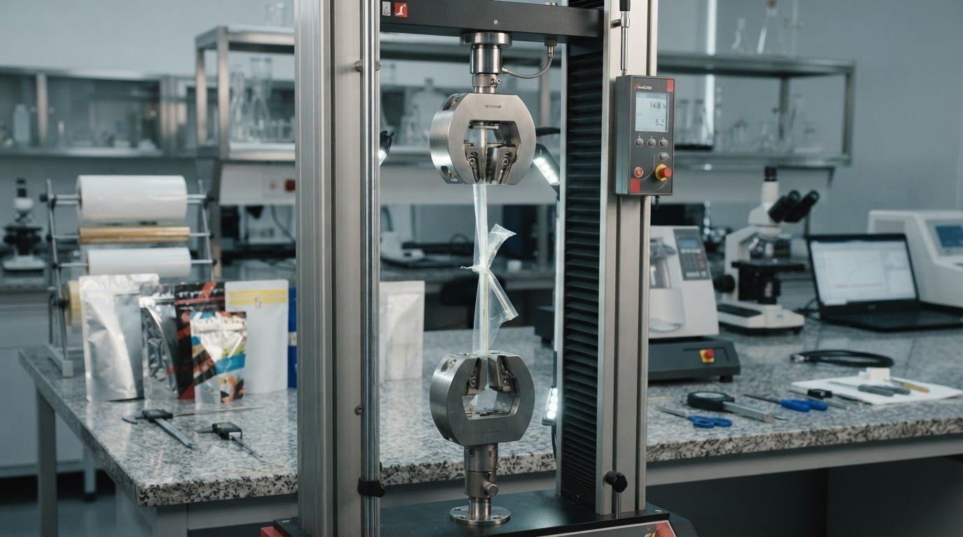
Implementing standardized peel strength testing for flexible packaging provides the empirical verification needed to resolve these structural vulnerabilities before high-speed converting and filling lines begin operation. Measuring peak peel force per unit width on a calibrated tensile testing machine—utilizing protocols such as a T-peel test method or an ASTM F88 seal strength evaluation—allows packaging engineers to validate adhesive curing, substrate surface energy treatments, and ink anchorage across multi-layer substrates.
The following breakdown clarifies how to interpret quantitative tensile data to establish measurable delamination resistance criteria, evaluate converter quality control protocols, and select composite structures capable of preserving seal and barrier integrity throughout complex distribution cycles.
Structural Mechanics of Interlayer Separation and Seal Failure in Flexible Barrier Materials
Flexible barrier packaging systems operate under demanding mechanical, thermal, and chemical stress profiles across global supply chains. In modern logistics, a multi-layer flexible packaging pouch or bag is subjected to compressive palletization loads, vibrational harmonics during transit, dropping shocks, and internal gas pressurization. The primary failure mechanisms that compromise containment are mechanical delamination across bonded plies and stress-induced degradation at the heat-sealed perimeter. When multi-layer films separate or heat seals rupture at the microscopic level, the structural integrity of the entire barrier system is forfeited, causing barrier loss against atmospheric gases, moisture ingress, and localized physical failure.
Primary Structural Separation Mechanisms:
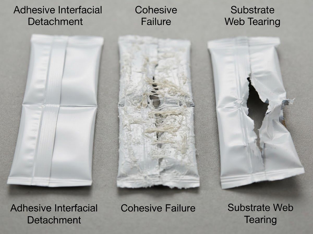
- Adhesive Failure: Boundary separation at the film-adhesive interface resulting from low substrate surface energy or corona decay.
- Cohesive Failure: Internal mechanical rupture within the adhesive layer or the bulk sealant polymer matrix.
- Substrate Tearing: Tensile yield and rupture of the base film web prior to interfacial separation, indicating optimal bond strength.
In industrial applications, particularly across demanding flexible food packaging formats, structural integrity depends directly on the balance between cohesive strength within individual plies and interfacial adhesion between dissimilar polymer webs. Delamination begins when external peel or shear stresses exceed the interfacial bond energy holding adjacent webs together. Once an interfacial crack initiates at a package edge, seam junction, or fold point, dynamic mechanical stress drives crack propagation along the bond line. This separation not only reduces the load-bearing capacity of the flexible packaging wall but also creates micro-voids where volatile organic compounds, moisture vapor, and atmospheric oxygen migrate freely.
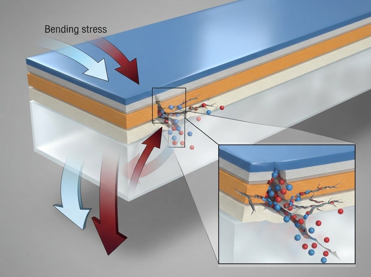
Environmental Stress Pathways:
- Thermal Cycling: Induces differential ply expansion, generating continuous interfacial shear stress.
- Vibrational Fatigue: Promotes micro-crack propagation, resulting in boundary delamination.
- Moisture Ingress: Triggers plasticization and hydrolysis, leading to the progressive loss of interlayer adhesion.
Delamination Vectors: Dynamic Mechanical Stress and Environmental Degradation
Delamination vectors originate from both mechanical loading and environmental degradation. Mechanical vectors are driven by dynamic shear stresses generated when flexible packaging is flexed, folded, or vibrated. When dissimilar substrates such as biaxially oriented polyethylene terephthalate (BOPET), aluminum foil, oriented polyamide (OPA/Nylon), and cast polyethylene (PE) are laminated together, each material exhibits a distinct modulus of elasticity and coefficient of thermal expansion (CTE).
When a multi-layer pouch is subjected to thermal swings during cold-chain warehousing or high-temperature ambient transport, these mismatched CTE values cause adjacent plies to expand or contract at unequal rates. This dimensional mismatch generates continuous planar shear stress along the adhesive boundary.
Degradation Vectors in Distribution:
- Mismatched CTE: Drives interfacial shear strain during temperature swings across dissimilar web materials.
- Hydrolytic Attack: Moisture migration plasticizes polyurethane adhesive bonds, weakening cross-link density.
- Cyclic Transport Vibration: High-frequency stress oscillations propagate existing micro-fractures along the bond interface.
Environmental degradation accelerates this mechanical destabilization. In high-humidity storage environments, moisture vapor can penetrate permeable outer polymer layers and accumulate at the adhesive interface. For solvent-based or solventless polyurethane laminating adhesives, prolonged exposure to moisture can induce hydrolytic degradation of polymer chains, plasticizing the adhesive matrix and reducing its shear modulus.
Simultaneously, cyclic transport vibrations introduce continuous, low-amplitude fatigue cycles. Over hundreds of transit miles, these high-frequency vibrational harmonics act directly on pre-existing micro-voids along the bond plane, steadily propagating microscopic fractures into macroscopic delamination zones without requiring a single catastrophic impact event.
Adhesive Failure vs. Cohesive Separation in Multi-Layer Packaging Seams
Evaluating seal and lamination integrity requires distinguishing between adhesive failure and cohesive separation. Adhesive failure, often termed interfacial failure, occurs when separation happens cleanly at the boundary between the adhesive matrix and the substrate web, or directly between two heat-sealed films without structural elongation.
This condition typically stems from inadequate surface preparation, such as an insufficient corona discharge treatment level (e.g., surface energy falling below 38 to 42 dynes/cm on polyolefin films), surface contamination, or severe migration of internal additives like slip agents (erucamide or oleamide) and anti-block particles to the interface, which prevent intimate molecular contact and secondary bonding.
Failure Mode Characteristics:
- Adhesive Failure: Clean interface detachment with minimal energy dissipation, indicating surface energy deficits, additive migration, or low corona treatment.
- Cohesive Failure: Internal fracture within the adhesive layer or sealant bulk with high energy dissipation, indicating balanced surface adhesion exceeding internal polymer shear strength.
- Film Tear / Substrate Yield: Complete web rupture before bond failure with maximum energy dissipation, confirming optimal lamination bond and seal integrity exceeding base film yield strength.
Cohesive failure occurs when the separation plane runs through the interior of the adhesive layer or the bulk polymer matrix of the heat-seal layer. In this mode, interfacial adhesion to both adjacent substrates exceeds the internal tensile or shear strength of the bonding material itself. Cohesive failure demonstrates that chemical cross-linking and surface wettability were sufficient to establish robust interfacial anchoring.
When conducting peel strength testing on fully cured, high-performance barrier laminates, engineers frequently observe substrate tearing or material yield before pure adhesive separation occurs. Quantifying whether a joint fails adhesively or cohesively provides the primary empirical diagnostic for determining whether a packaging fault originates from surface energy deficits, chemical under-curing, or excessive mechanical line tension during pouch converting.
Standardized Methodologies for Peel Strength Testing for Flexible Packaging
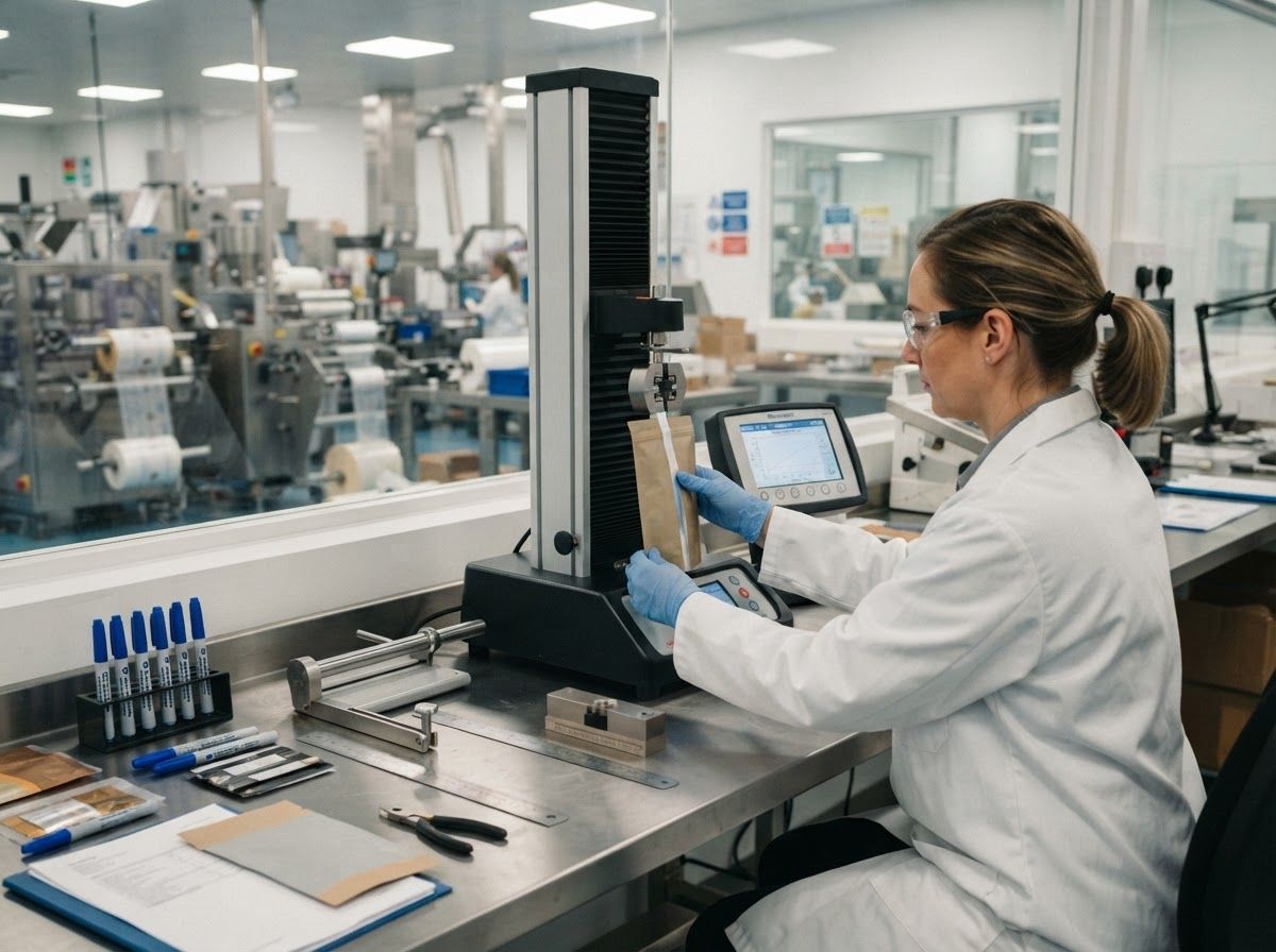
Quantifying interfacial bonding forces and seal integrity requires standardized mechanical testing executed on high-precision tensile testing machines equipped with sensitive low-capacity load cells (typically 10 N to 500 N). Standardized testing protocols eliminate subjective manual peel assessments by strictly controlling specimen geometry, peel angle, grip separation rate, and environmental conditioning.
The primary international test protocols governing flexible packaging materials include ASTM F88 (Standard Test Method for Seal Strength of Flexible Barrier Materials), ASTM D1876 (Standard Test Method for Peel Resistance of Adhesives, commonly known as the T-Peel Test), and standardized 180-degree peel test procedures.
Standardized Testing Configurations:
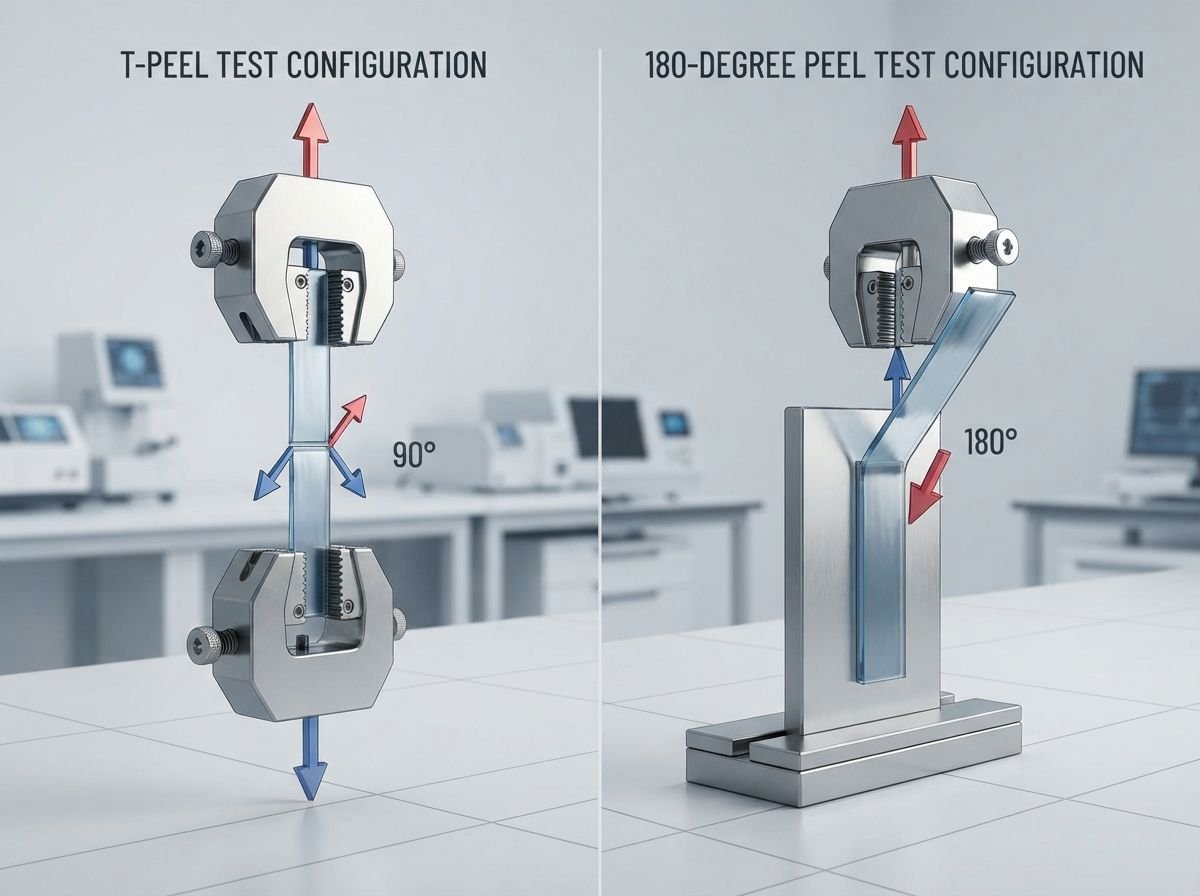
- ASTM D1876 (T-Peel): Both flexible arms bent at 90 degrees to the bond line (180 degrees total included angle).
- 180-Degree Peel: Flexible ply stripped back 180 degrees against a semi-rigid or rigid backing plate.
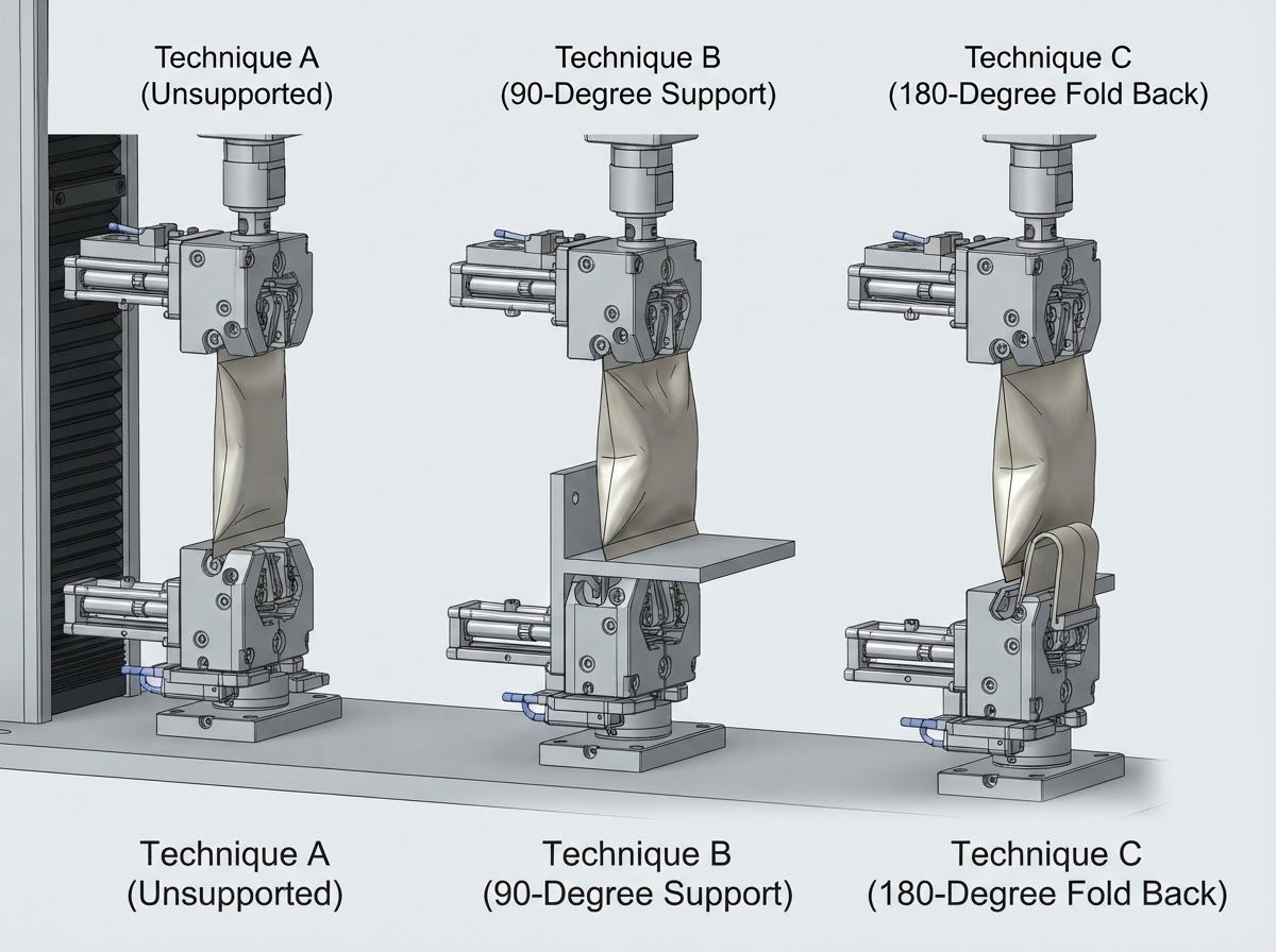
- ASTM F88 Technique A (Unsupported): Opposing seal tails clamped freely with unconstrained bending.
- ASTM F88 Technique B (90° Supported): Seal body supported manually or mechanically at 90 degrees to the pull axis.
- ASTM F88 Technique C (180° Supported): Sealed tail folded back and clamped parallel to the moving grip.
Specimen preparation requires strict precision to avoid micro-nicks, edge tearing, or non-parallel edges that distort tensile curves. Test strips are cut using precision double-blade sample cutters to standard widths, typically 15 mm (0.59 inches) or 25.4 mm (1.0 inch). Prior to testing, specimens must be conditioned under controlled atmospheric conditions—typically 23 degrees Celsius (+/- 2 degrees Celsius) and 50% relative humidity (+/- 5% RH)—for a minimum of 24 to 48 hours to stabilize polymer moisture content and relieve residual processing stresses.
Grip separation rates are maintained at controlled speeds, standardly between 200 mm/min and 300 mm/min (8 to 12 inches/min), ensuring consistent strain-rate response across viscoelastic polymer matrices.
| Standard Protocol | Grip & Specimen Geometry | Tail Support Fixture | Primary Target Metric | Parasitic Bending Energy Interference | Best-Fit Industrial Application |
|---|---|---|---|---|---|
| ASTM D1876 (T-Peel) | Opposing plies bent at 90° from bond line into opposing grips | Unsupported; symmetric T-shape configuration | Laminate interlayer bond strength across flexible webs | Moderate; dependent on flexural stiffness of both webs | Measuring inter-ply lamination adhesion in multi-layer barrier rollstock |
| 180° Peel Test | Flexible film peeled back flat against a rigid or semi-rigid substrate | Backing substrate secured in stationary bottom grip | Interfacial adhesion of tape, label, or film-to-foil bonds | Low to High; driven by bending radius of peeled web | Evaluating metallized coatings, label stock, and rigid-backed barrier plies |
| ASTM F88 Technique A | Seal tails secured in opposing grips in a straight vertical line | Unsupported; tails hang freely during crosshead displacement | Maximum seal force and seal opening behavior | High; includes unconstrained tail bending and rotation energy | Quick screening of pouch seals; flexible films with low flexural modulus |
| ASTM F88 Technique B | Opposing seal tails clamped; sealed pouch body supported at 90° | Supported at 90° via manual hold or mechanical fixture | Pure seal interface tensile yield under normal orientation | Minimal; isolates seal line by removing gravitational tail sag | High-accuracy validation of retort and modified atmosphere packaging seams |
| ASTM F88 Technique C | Least flexible tail clamped with sealed body folded back 180° | Supported at 180° against moving or stationary grip | Maximum resistance to peel-back seam propagation | Moderate; incorporates 180° bending moment of one film arm | Form-fill-seal (FFS) fin seals and lap seals subjected to peel opening forces |
The data generated across these standardized protocols directly guide raw material qualification and converter machine setup. When evaluating high-barrier structures, packaging engineers must select the specific protocol that replicates the primary stress vector encountered in the field.
For instance, ASTM D1876 is the definitive protocol for quantifying adhesive lamination integrity across two flexible substrates, whereas ASTM F88 isolates the mechanical performance of heat-activated fusion seams. Selecting the appropriate tail support technique prevents erroneous pass/fail classifications caused by substrate bending stiffness rather than true seal bond strength.
T-Peel Test Method vs. 180-Degree Peel Test Configurations for Lamination Bond Strength
The fundamental mechanical distinction between the T-peel test (ASTM D1876) and the 180-degree peel configuration lies in the vector distribution of applied tensile forces and the bending deformation imposed on the test arms. In a T-peel configuration, both laminated plies are flexible and are clamped into opposing tensile grips such that each arm bends at approximately 90 degrees relative to the unseparated lamination plane, forming a symmetric “T” profile. As the crosshead moves, tensile force acts equally to pull both substrates away from the central adhesive bond line.
This method is well-suited for evaluating flexible-to-flexible multi-layer structures, such as polyethylene-to-polyester or polyamide-to-polyethylene duplex laminates, because both plies share mechanical deformation symmetrically.
In contrast, a 180-degree peel test clamps one substrate in a flat, vertical orientation—frequently secured to a rigid metal plate or semi-rigid backing sheet—while the second flexible substrate is folded completely backward and peeled parallel to the bond plane. The 180-degree configuration concentrates peel stress tightly at the immediate peeling apex.
However, this setup introduces significant parasitic bending energy: the energy recorded by the load cell reflects not only the chemical and mechanical work of interfacial adhesion separation, but also the plastic and elastic work required to bend the flexible ply across a tight 180-degree radius. When testing stiff substrates like thick aluminum foil or high-density polyethylene (HDPE), these parasitic bending resistance forces can distort raw tensile readings if not mathematically decoupled or mechanically standardized.
ASTM F88 Seal Strength Protocols and Tail Support Mechanics
ASTM F88 specifies three distinct clamping techniques—Technique A (Unsupported), Technique B (90-Degree Supported), and Technique C (180-Degree Supported)—to evaluate the seal strength of flexible barrier materials. The choice of technique directly alters how stress concentrates at the inner seal margin, where failure typically initiates in pressurized or dropped packages.
In Technique A, the tail ends of the specimen are clamped into upper and lower pneumatic grips without external stabilization. As tensile load increases, the specimen tails rotate freely toward the center line of pull. This unconstrained rotation generates mixed-mode loading, combining pure tensile opening forces with out-of-plane shear and bending moments.
Technique B provides greater mechanical consistency by supporting the tail of the sealed pouch at a strict 90-degree angle relative to the applied tensile axis throughout crosshead travel. This orientation isolates the opening force to a pure normal peel mode at the seal margin, removing tail sagging and parasitic rotational forces. Technique B is often specified in validated medical and retort food packaging quality programs.
Technique C folds the less flexible tail backward against the advancing grip, generating a 180-degree peeling mode. When testing high-extensibility sealant films like linear low-density polyethylene (LLDPE) or cast polypropylene (CPP), the engineer must distinguish true seal separation from plastic elongation (necking) of the film body. If elongation begins before the seal opens, the tensile curve will capture material yield energy rather than true interfacial seal strength.
Interpreting Tensile Curves: Extracting Laminate Bond Strength Test Data
A force-displacement tensile curve generated by a calibrated tensile testing machine provides a continuous physical record of material behavior during seam separation. A comprehensive analysis of this curve goes beyond merely recording the single highest force peak; it extracts quantifiable data spanning the entire delamination process.
The tensile curve typically exhibits four distinct mechanical phases: the initial linear-elastic ramp, where tensile stress builds within the specimen arms; the peak initiation force, representing the threshold energy required to initiate boundary separation; the steady-state propagation plateau, representing the continuous average peel force per unit width across the bonded area; and the termination drop-off, where the plies separate completely.
The primary engineering metrics derived from this curve are maximum peak peel force and average propagation peel force, both normalized across the specimen width and expressed in units of N/15mm, N/25.4mm, or lbf/in.
While the peak initiation force indicates a package’s transient resistance to hydraulic burst shocks (such as during drop impacts), the average propagation plateau measures the uniform quality of adhesive coverage, surface wetting, and cross-linking density across the web.
Connecting curve anomalies directly to converting parameters allows quality engineers to resolve manufacturing defects efficiently. High-frequency serrations (stick-slip behavior) point toward localized variations in adhesive modulus or uneven plasticizer migration.
Conversely, a sudden load drop during steady-state peeling signals localized unbonded patches, unevaporated solvent pockets, or complete ink detachment beneath reverse-printed films. For challenging structures such as an aluminum foil laminated film roll, tracking tensile curve stability ensures that brittle foil layers remain firmly bonded to adjacent polymer films without micro-fracturing under high-speed tension.
Key Processing Defects Indicated by Curve Profiles:
- Low Flat Plateau: Points to an inadequate polyisocyanate curing ratio or decayed surface energy (<38 dynes/cm).
- Erratic Spikes and Valleys: Reflects uneven adhesive coat weight distribution or gravure cylinder clogging.
- Sudden Step-Down Drop: Signals ink anchorage failure, where reverse-printed ink shears away from the carrier film.
Peak Peel Force per Unit Width vs. Average Propagation Resistance
Differentiating between peak peel force and average propagation resistance is essential for establishing sound packaging design margins. The peak peel force reflects the maximum instantaneous force registered by the load cell during the entire test sequence, which almost invariably occurs at the initial crack-opening edge.
This peak value is heavily influenced by edge geometry, local meniscus formation of adhesive fillets, and mechanical stress concentration factors. In practical applications, high peak peel force prevents pouches from bursting open when dropped from pallet heights or subjected to external mechanical compression.
However, relying solely on peak force can yield false positives regarding overall lamination quality. A packaging web may exhibit a high initial peak force due to an over-glued or heat-concentrated edge, yet fail rapidly across its main body due to an inadequate average propagation resistance.
The average propagation resistance is calculated by mathematically integrating the area under the force-displacement curve across the steady-state peeling zone—standardly defined as the middle 80% of total peeling displacement, explicitly discarding the initial 10% initiation transient and the final 10% edge-termination drop:
- Discard Initial 0% to 10%: Eliminates initiation transients and grip settling artifacts.
- Integrate Middle 10% to 90%: Calculates total area under the curve across the steady-state plateau.
- Derive Average Peel Force: Divides integrated energy by displacement distance to determine average peel resistance (N/15mm).
- Discard Final 90% to 100%: Removes edge release drop-off distortions.
This averaging algorithm removes clamping settling artifacts, localized edge deviations, and operator handling noise, providing an accurate measure of thermodynamic work of adhesion and cohesive polymer performance per unit width.

Diagnostic Curve Profiles: Identifying Inadequate Curing, Surface Energy Deficits, and Ink Delamination
Interpreting anomalous tensile curve profiles allows packaging engineers to pinpoint root-cause defects in lamination, printing, and corona treatment processes:
- Flat, Low-Magnitude Plateaus: When the tensile profile exhibits a flat plateau that tracks well below the specified engineering threshold, the defect typically indicates either incomplete chemical cross-linking of the polyurethane adhesive or insufficient corona treatment on non-polar polyolefin films. If two-component polyurethane adhesives are mixed off-ratio (e.g., an isocyanate-to-polyol imbalance) or cured under sub-optimal room temperatures, the cross-linking density remains low. This manifests as a clean, effortless adhesive peel with minimal force resistance. Similarly, if film surface energy drops below 38 dynes/cm, secondary molecular bonding fails across the entire web.
- Erratic “Shocking” Profiles (High-Amplitude Oscillations): When the tensile curve displays erratic spikes alternating with deep valleys, the material suffers from physical inconsistencies in adhesive application. Common causes include partially blocked gravure cylinder cells, mechanical chatter on coating rollers, or uneven adhesive coat weights across the web width. This profile can also indicate pockets of unevaporated retained solvent, which disrupt continuous adhesive film formation.
- Step-Down Drop-Offs (Ink Anchorage Failure): When testing reverse-printed laminates (e.g., printed BOPP or PET laminated to PE), a curve may initiate with acceptable force resistance before stepping down sharply to a near-zero plateau. Visual inspection of the delaminated specimen typically shows the ink layer completely stripped off the primary film carrier and adhering to the sealant ply. This profile confirms an ink anchorage failure, caused by missing primer coatings, mismatched ink resin systems, or surface treatment decay on the print web prior to ink application.
Multi-Layer Composite Laminates vs. Single-Layer Films Under Mechanical Load
Monolayer (single-layer) polymer films are fundamentally limited in their mechanical and barrier capabilities. When a single-layer film (such as monolayer low-density polyethylene or polypropylene) is subjected to tensile, puncture, or flexural loading, applied stresses concentrate directly at localized material flaws, notch points, or heat-seal junctions.
Without internal layer boundaries to redirect crack energy, a micro-crack initiated at a heat-seal notch propagates rapidly through the entire cross-section of the single film, resulting in sudden, catastrophic package failure. Furthermore, single-layer films cannot simultaneously optimize conflicting performance demands, such as high tensile stiffness, superior gas barrier protection, low-temperature seal initiation, and high heat resistance.
Multi-layer composite laminates resolve these mechanical constraints through interlayer load distribution:
- Outer Structural Web (e.g., BOPET/BOPP): Provides dimensional stability, heat resistance, and tensile stiffness.
- Core Barrier Ply (e.g., Aluminum Foil/OPA/EVOH): Delivers gas and moisture barrier properties while transferring shear across adhesive layers.
- Inner Sealant Layer (e.g., LLDPE/CPP): Facilitates fusion sealing at low initiation temperatures and dissipates plastic deformation energy.
When mechanical loads are applied to a multi-layer laminate, the adhesive layers act as shear-transfer media, distributing localized stresses across the wider surface areas of adjacent plies. This mechanical synergy prevents stress concentration at the seal notch and prevents micro-cracks from propagating through the entire barrier assembly.
| Structural Configuration | Interlayer Shear Transfer Mechanism | Seal Notch Stress Concentration | Flex-Crack Barrier Retention (WVTR / OTR) | Typical Peel Force Range (N/15mm) | Primary Failure Mode Under Ultimate Load |
|---|---|---|---|---|---|
| Monolayer Film (e.g., Monolayer LDPE/LLDPE) | None; single homogenous polymer matrix | Extreme; notch crack propagates directly through film wall | Very Poor; pinholes and tears immediately breach total barrier | Not Applicable (No laminate interface) | Fast brittle or ductile notch tear across the film body |
| 2-Ply Duplex Laminate (e.g., BOPP/CPP, PET/PE) | Interfacial adhesive layer transfers shear strain across webs | Moderate; elastic sealant ply blunts crack growth | Moderate; depends on polymer crystal orientation stability | 1.5 to 4.0 N/15mm (or film tear) | Cohesive adhesive peel or plastic stretching followed by film yield |
| 3-Ply High-Barrier Foil Laminate (e.g., PET/AL/PE) | Dual adhesive layers buffer brittle core foil against shear strain | Low; outer and inner plies absorb structural energy | High; robust bond prevents micro-fracturing of brittle AL foil | 2.5 to 5.5 N/15mm (or foil tear) | Interfacial peel or foil fracture with substrate delamination |
| 4-Ply Retort / Heavy-Duty Laminate (PET/OPA/AL/CPP) | Tri-adhesive interface distributes high dynamic dynamic shocks | Minimal; polyamide (OPA) ply blunts puncture and drop energy | Maximum; high-modulus adhesive prevents foil-flex pinholing | > 4.5 N/15mm (High bond strength requirement) | Substrate elongation, deep cohesive yield, or structural film tear |
The mechanical distinctions detailed in the table emphasize why rigorous peel testing is vital when converting high-speed materials like a laminated flexible film roll.
If lamination bond strength is substandard, the differential shear stress between the outer oriented film and the inner sealant web will trigger edge delamination during forming. This delamination jams packaging equipment and compromises the integrity of finished package seams.
Barrier Ply Protection in Aluminum Foil and Vacuum-Metallized Laminates
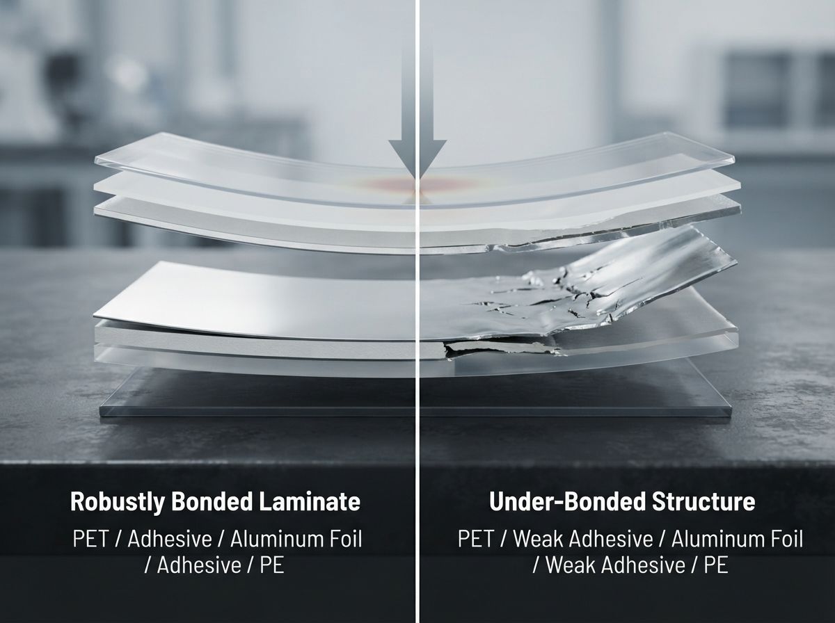
Aluminum foil (typically 7 microns to 9 microns in thickness) and vacuum-metallized polymer substrates (such as metallized PET or metallized BOPP) offer gas and moisture barrier properties. However, these barrier plies are mechanically rigid and brittle. When bent, creased, or flexed during pouch converting, shipping vibration, or handling, unbonded or poorly bonded aluminum foil quickly develops micro-pinholes and flex-cracks.
Robust interlayer peel strength protects these fragile barrier plies:
- High Interlayer Bond Strength: Compressive and tensile stresses are transferred smoothly to elastic polymer layers, mechanically supporting the foil layer and keeping Water Vapor Transmission Rate (WVTR) and Oxygen Transmission Rate (OTR) stable.
- Low Interlayer Bond Strength: Foil flexes independently of supporting polymer webs, allowing localized cyclic fatigue to induce micro-pinholing, metal cleavage, and rapid barrier degradation.
When bonded with a high-modulus adhesive, the surrounding elastic polymer layers—such as oriented polyamide (OPA) or tough polyethylene—mechanically support the brittle barrier layer. As the package flexes, the high-strength adhesive layer transfers bending strain smoothly across the entire laminate cross-section, preventing localized stress concentrations in the metal or metallized coating.
Conversely, if peel strength is insufficient, the foil layer flexes independently of the adjacent polymer films, experiencing severe localized fatigue that causes premature pinholing and delamination. This failure directly degrades the package’s WVTR and OTR, leading to oxygen ingress, moisture loss or absorption, and premature product degradation.
Seal Integrity and Seam Stress Distribution in Finished Pouch Converting
In converted pouch formats—including three-side seal pouches, side-gusset bags, and stand-up pouches—the junction where the heat-sealed perimeter meets the unsealed pouch body is the primary point of stress concentration. When a filled pouch experiences impact shocks during drop events or top-load stacking compression, internal hydraulic or pneumatic pressure forces product against these interior seal edges.
If interlayer lamination bond strength is low, this internal hydraulic surge drives the outer plies to peel away from the inner sealant ply at the seal margin—a failure mode termed “delamination at the seal notch.” Once outer structural webs pull away from the sealant layer, the thin, unsupported sealant film quickly stretches and bursts under minimal internal pressure.
Conversely, when lamination peel strength is robust, the inner sealant layer and outer structural webs act as a unified, reinforced composite. Impact stresses are distributed through the full cross-sectional thickness of the laminate, blunting crack propagation at the seal notch. For robust packaging styles such as a multi-layer laminated stand-up pouch, high peel and seal strength prevent seam splitting, flex cracking, and perimeter delamination under demanding logistics and stacking pressures.
Executing Rigorous Peel Strength Testing for Flexible Packaging Across Quality Control Protocols
Implementing standardized peel and seal strength testing requires an operational framework that bridges technical data sheets (TDS), incoming material quality control (IQC), and converting-line process adjustments. Packaging converters and commercial brand owners must establish statistically validated testing protocols rather than relying on sporadic, single-specimen tests.
Incoming rollstock must be sampled according to established Acceptable Quality Level (AQL) standards (such as ISO 2859-1 or ANSI/ASQ Z1.4), with testing intervals distributed systematically across the start, middle, and end of master rolls to account for cross-web and machine-direction coating variations.
Core Quality Control Architecture:
- Rollstock Sampling: Execute AQL statistical sampling across the start, middle, and end of master reels, conducting separate Machine Direction (MD) and Transverse Direction (TD) strip tests.
- Curing Age Validation: Maintain a mandatory 24-hour to 72-hour curing hold for solventless polyurethane systems before release testing; confirm complete solvent evacuation on solvent-based laminations.
- Quantifiable Acceptance Criteria: Require a minimum average peel force threshold (e.g., > 3.0 N/15mm or Substrate Tear), prohibiting clean interfacial adhesive peeling below baseline limits.
Testing protocols must independently evaluate specimens cut along both the Machine Direction (MD) and the Transverse Direction (TD). Because polymer orientation, web tension during lamination, and adhesive coating smoothing bars introduce directional anisotropy, peel values can vary between MD and TD axes.
Furthermore, when evaluating solventless polyurethane adhesive systems, quality control procedures must account for curing kinetics. Testing rollstock immediately off the lamination line will show artificially low peel values because the polyisocyanate prepolymers require a 24-hour to 72-hour room-temperature or hot-room curing hold to achieve complete chemical cross-linking and reach ultimate bond strength.
| Observed Failure Symptom | Failure Mode Classification | Probable Converting / Material Root Cause | Immediate Plant-Floor Corrective Action |
|---|---|---|---|
| Low Peel Force with Clean Interfacial Separation | Interfacial Adhesive Failure | Surface energy of polyolefin web below critical wetting threshold (<38 dynes/cm) | Re-verify corona treater power; replace decayed base film rolls; check dyne levels |
| Low Bond Strength with Soft, Tacky Adhesive Residue | Cohesive Adhesive Failure (Under-cured) | Off-ratio mixing of 2K polyurethane adhesive; low curing temperature or high moisture | Recalibrate adhesive dispensing pumps; extend hot-room curing time (40°C–50°C) |
| Reverse-Printed Ink Stripping Completely off Carrier Web | Ink Anchorage Failure | Missing primer; incompatible ink-resin chemistry; print-side corona decay | Apply chemical adhesion-promoter primer; reformulate ink system; check print-web dyne |
| Brittle Interlayer Peeling with High Stick-Slip Serration | Micro-void Cohesive Failure | Uneven adhesive coat weight; gravure cylinder cell clogging; rapid solvent flash-off | Deep-clean gravure coating cylinder; adjust drying tunnel air balance and temperature |
| Seal Opens at Very Low Force with Zero Substrate Elongation | Cold Seal / Non-Fusion Seam Failure | Sealing temperature below Seal Initiation Temperature (SIT); low jaw dwell time | Increase heat-seal bar temperature; verify jaw pressure and parallelism; increase dwell |
| Film Delaminates Specifically at the Seal Border Notch | Notch-Induced Shear Delamination | Slip additive (erucamide) migration from sealant bulk to adhesive interface | Switch to non-migratory slip additives or low-slip PE grades; adjust curing thermal cycle |
The troubleshooting matrix provides operational guidance that connects force-displacement data into corrective actions on the plant floor. By linking specific failure profiles directly to converting variables—such as corona levels, adhesive stoichiometric ratios, and seal-jaw mechanics—engineering teams can resolve manufacturing variations before non-compliant packaging reaches commercial filling operations.
Establishing Measurable Procurement Specifications and Converter Validation Baselines
Procurement specifications that state generic terms like “adequate lamination bond” or “strong seal strength” leave packaging buyers exposed to commercial and operational risk. High-reliability procurement programs define unambiguous, quantitative criteria within technical data sheets (TDS).
These specifications must detail the minimum acceptable average peel force (expressed in N/15mm or N/25.4mm), the governing test standard (e.g., ASTM D1876, ASTM F88 Technique B), specimen cutting directions (MD and TD), and required failure mode classifications.
Procurement TDS Specification Guidelines:
- Minimum Target: Average Laminate Bond Strength >= 3.5 N/15mm (or Substrate Tear).
- Governing Standard: ASTM D1876 / ASTM F88 Technique B.
- Crosshead Speed: 250 mm/min (+/- 10 mm/min).
- Sampling Frequency: 5 strips MD and 5 strips TD per master roll.
- Target Failure Mode: Substrate Film Tear or Cohesive Polymer Yield.
- Conditioning Standard: 23°C (+/- 2°C) and 50% RH (+/- 5% RH) for 48 hours.
A robust procurement baseline mandates specific acceptable failure modes. For example, a technical specification may require that a PET/AL/PE triplex laminate achieve a minimum peel strength of 3.0 N/15mm, with the explicit condition that substrate tearing or foil elongation is the only acceptable failure mode at higher forces.
If interfacial separation occurs below this threshold, the batch is automatically rejected. Establishing measurable procurement baselines ensures that converting facilities maintain tight control over resin selection, adhesive coat weights, and surface energy treatments.
Engineering Troubleshooting for Low Bond Strength and Premature Seam Delamination
When laboratory tensile testing identifies sub-standard peel or seal strength, quality teams must follow a systematic diagnostic sequence:
- Surface Energy Verification: Using calibrated dyne solution pens (in accordance with ASTM D2578), test the non-laminated surfaces of the base substrates. If the polyolefin sealant film or PET print film displays a surface energy below 38 to 42 dynes/cm, the base material has suffered corona decay or insufficient treatment at the extrusion stage. This requires adjusting corona treater output power or replacing degraded raw material rolls.
- Adhesive Stoichiometry and Curing Audits: If surface energy is acceptable but the adhesive layer remains soft or tacky, inspect the two-component adhesive mixing unit. An excess of polyol resin relative to the isocyanate hardener leaves unreacted functional groups, halting polymer network cross-linking. Verify curing room parameters (maintaining temperatures between 40 degrees Celsius and 50 degrees Celsius for solventless adhesives) to confirm that chemical kinetics can reach completion.
- Additive Migration Analysis: In polyolefin sealant films formulated with fatty acid amides (such as erucamide or oleamide) for friction reduction, high warehouse temperatures can accelerate additive bloom. These slip agents migrate out of the polyethylene core and accumulate at the lamination boundary, forming a weak boundary layer that prevents adhesive bonding. If chemical analysis (such as FTIR or GC-MS surface washing) confirms slip additive interference, the sealant formulation must be replaced with a low-migratory slip system or a high-density resin grade that restricts additive mobility.
- Heat-Seal Jaw Mechanical and Thermal Calibration: If peel testing along converted pouch seams demonstrates premature seal opening, technicians must calibrate the heat-sealing apparatus. Using thin thermocouple sensors and pressure-sensitive tactile film, measure the temperature uniformity and mechanical parallelism across the entire surface of the sealing jaws. Inconsistent jaw pressure or temperature drops along the sealing bar create cold spots where polymer chains cannot interdiffuse across the interface, leading to low seal strength and package failure under field distribution stresses.
Conclusion
Standardized peel and seal strength testing provides the empirical basis for validating multi-layer composite integrity and protecting sensitive barrier plies from mechanical transit stress. Analyzing force-displacement curves enables converters and brand owners to distinguish between adhesive boundary separation and cohesive material yield, establishing quantifiable thresholds rather than subjective assessments. Integrating standardized ASTM protocols and failure-mode criteria into incoming technical data sheets eliminates converting defects caused by surface energy deficits, under-curing, or slip additive migration. To evaluate barrier performance requirements and establish testing baselines for specific packaging formats, consult technical packaging specialists.


0 Comments